Silicon IP Cores
I3C-T
MIPI I3C Basic Target
The I3C-T core implements a versatile MIPI® Improved Inter Integrated Circuit (I3C) Target controller core suitable for any I3C bus topology & compliant with the latest MIPI I3C-BasicSM specification.
The highly featured target-only core communicates in Single Data Rate (SDR) mode, but can tolerate High Data Rate (HDR) traffic. It can coexist and communicate with legacy I2C devices, and it can optionally be configured to operate as such in an I3C or I2C bus. The I3C-T needs no firmware support to parse and execute the broadcast or direct Common Command Codes (CCCs) relevant to I3C Basic Targets. It can be assigned a Dynamic Address by the bus controller, or use its legacy I2C static address, it supports Hot Join and is capable of generating In-Band Interrupts when directed by the host to do so.
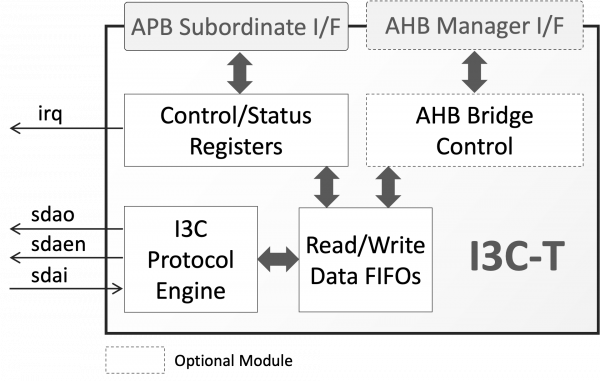
Designed for easy integration, the I3C-T can operate in two different modes. Under normal mode, data from private I3C or legacy I2C write transfers are stored to a FIFO, and made available to the host via an APB subordinate interface. In a similar way, the host provides data to be used for private I3C or legacy I2C read transfers via the core’s APB subordinate interface. Alternatively, the core can operate in I3C-to-AHB bridging mode, where it autonomously converts private I3C or legacy I2C transfers to accesses on its AHB manager port using a simple yet configurable over-I3C protocol. Under the I3C-to-AHB bridging mode, the core needs no software assistance and provides the I3C-controller access to the local AHB bus, enabling remote monitoring, configuration, debug, or data exchange. The selection between normal and bridging operation modes is under software control via the core’s control register.
The highly flexible core offers synthesis-time and run-time configuration options, which allow adapting its size and behavior to the application requirements. For example, the AHB-manager interface and the clock domains synchronizers can be removed at synthesis time to reduce the core’s silicon footprint. During run-time, the I3C private data and I2C traffic can be bridged to the core's AHB manager interface or transferred to and from the host via the core's APB subordinate interface. Also, parameters defining the CCCs processing (e.g. own-address, provisional ID, acknowledge for different type CCCs), the over-I3C protocol (i.e. number address bytes, max number of data bytes), and the AHB-manager port behavior (e.g AHB burst type & address wrapping) are all run-time configurable via the core’s registers.
The I3C-T core adheres to the industry’s best coding and verification practices to ensure trouble-free implementation in ASIC or FPGA technologies. Technology mapping, constraining, and scan insertion are straight-forward, as the core contains no multi-cycle or false paths, and uses only rising-edge-triggered D-type flip-flops, no tri-states, an asynchronous reset line per clock domain, and clean clock domain crossing modules. Its reliability and low risk have been proven through rigorous verification and FPGA validation.
The core is available in synthesizable Verilog format or as a targeted FPGA netlist, and its deliverables include everything required for successful implementation, including a system-Verilog test-bench, synthesis, and simulation scripts, and comprehensive documentation.
The MIPI I3C Basic specification is a subset of the MIPI I3C Specification that is publicly accessible and intended to be implementable by non-MIPI organizations under a RAND-Z license.
The Royalty-free MIPI I3C Basic provisions a multidrop two-wire serial bus operating up to 12.5MHz, that provides many of the I3C protocol innovations, including in-band interrupts, dynamic address assignment and backward compatibility with I2C.
Learn more at MIPI I3C official web page.
The I3C-S can be mapped to any ASIC technology or FPGA device, provided sufficient resources are available. The following table provides sample silicon resources utilization data. Please contact CAST to get characterization data for your target configuration and technology.
| Technology | Configuration | Area |
|---|---|---|
| TSMC 7nm | Minimum | 5,496 eq. Gates |
| Full, without CDC, 32x16 FIFOs | 17,354 eq. Gates | |
| Full, with CDC, 32x16 FIFOs | 21,429 eq. Gates |
The I3C-S can be mapped to any Altera® FPGA device, provided sufficient resources are available. The following table provides sample silicon resources utilization data. Please contact CAST to get characterization data for your target configuration and technology.
| FPGA Family | Configuration | Resources |
|---|---|---|
| Cyclone® V | Minimum | 1,182 ALMs |
| Full, without CDC, 32x16 FIFOs | 2,520 ALMs | |
| Full, with CDC, 32x16 FIFOs | 2,667 ALMs | |
| Stratix® V | Minimum | 1,189 ALMs |
| Full, without CDC, 32x16 FIFOs | 2,533 ALMs | |
| Full, with CDC, 32x16 FIFOs | 2,674 ALMs | |
| Arria® 10GX | Minimum | 829 ALMs |
| Full, without CDC, 32x16 FIFOs | 1,680 ALMs | |
| Full, with CDC, 32x16 FIFOs | 1,739 ALMs | |
| Max® 10 | Minimum | 1,461 LEs |
| Full, without CDC, 32x16 FIFOs | 3,995 LEs | |
| Full, with CDC, 32x16 FIFOs | 4,617 LEs |
The I3C-S can be mapped to any AMD FPGA device, provided sufficient resources are available. The following table provides sample silicon resources utilization data. Please contact CAST to get characterization data for your target configuration and technology.
| FPGA Family | Configuration | Resources |
|---|---|---|
| Kintex™ 7 | Minimum | 882 LUTs |
| Full, without CDC, 32x16 FIFOs | 2,432 LUTs | |
| Full, with CDC, 32x16 FIFOs | 2,493 LUTs | |
| Kintex™ Ultrascale | Minimum | 897 LUTs |
| Full, without CDC, 32x16 FIFOs | 2,280 LUTs | |
| Full, with CDC, 32x16 FIFOs | 2,473 LUTs | |
| Kintex™Ultrascale+ | Minimum | 897 LUTs |
| Full, without CDC, 32x16 FIFOs | 2,280 LUTs | |
| Full, with CDC, 32x16 FIFOs | 2,473 LUTs |
The I3C-S can be mapped to any Lattice FPGA device, provided sufficient resources are available. The following table provides sample silicon resources utilization data. Please contact CAST to get characterization data for your target configuration and technology.
| FPGA Family | Configuration | Resources |
|---|---|---|
| ECP5 | Minimum | 1,403 LUT4 / 501 Slices |
| Full, without CDC, 32x16 FIFOs | 1,423 LUT4 / 1,047 Slices | |
| Full, with CDC, 32x16 FIFOs | 3,514 LUT4 / 2,702 Slices | |
| MachXO2 | Minimum | 1,400 LUT4 / 703 Slices |
| Full, without CDC, 32x16 FIFOs | 1,424 LUT4 / 718 Slices | |
| Full, with CDC, 32x16 FIFOs | 3,529 LUT4 / 1,768 Slices | |
| ICE40 HX | Minimum | 1,891 LUT4 / 2,038 LCs |
| Full, without CDC, 32x16 FIFOs | 2,114 LUT4 / 2,266 LCs | |
| Full, with CDC, 32x16 FIFOs | 5,618 LUT4 / 5,780 LCs |
The I3C-S can be mapped to any Microchip FPGA device, provided sufficient resources are available. The following table provides sample silicon resources utilization data. Please contact CAST to get characterization data for your target configuration and technology.
| FPGA Family | Configuration | Resources |
|---|---|---|
| Igloo2 | Minimum | 1,352 4LUT / 1,377 LEs |
| Full, without CDC, 32x16 FIFOs | 1,395 4LUT / 1,546 LEs | |
| Full, with CDC, 32x16 FIFOs | 3,815 4LUT / 4,423 LEs | |
| PolarFire | Minimum | 1,342 4LUT / 1,460 LEs |
| Full, without CDC, 32x16 FIFOs | 1,395 4LUT / 1,512 LEs | |
| Full, with CDC, 32x16 FIFOs | 3,815 4LUT / 4,425 LEs | |
| ProASIC3 | Minimum | 2,728 CORE / 454 SEQ |
| Full, without CDC, 32x16 FIFOs | 2,930 CORE / 744 SEQ |
Support
The core as delivered is warranted against defects for ninety days from purchase. Thirty days of phone and email technical support are included, starting with the first interaction. Additional maintenance and support options are available.
Verification
The core has been rigorously verified through extensive synthesis, place and route, simulation runs, with in-house and 3rd party verification. The core is silicon-proven.
Engineered by Silesia Devices.
Features List
I3C Features
- I3C-Basic, up to 12.5 Mbit/s SDR-Capable and HDR-Tolerant Target
- Autonomous processing of all Broadcast and Direct Common Command Codes (CCCs) relevant to an I3C-Basic target.
- Hot-Join Mechanism
- In-Band Interrupts I3C Bus and Device Characteristic Registers (BCR & DCR),
- Dynamic Addressing Assignment
- Optional operation as a legacy I2C device, and interoperable with legacy I2C devices
- Supports I2C static addressing, I2C messaging, and a 50ns spike filter
Easy to Use & Integrate
- Run-time selectable operation modes:
- Autonomous I3C-to-AHB bridge
- Firmware-assisted, I3C controller exchanging data with the host via APB-accessible registers, or implementing a custom over-I3C protocol
- Standardized AMBA interfaces
- APB-Subordinate for register access
- AHB-Manager (when I3C-to-AHB bridging mode is enabled)
- Independent clocks for APB. AHB and I2C with clean clock domain crossing
- Fully synchronous, scan-ready, LINT-clean design
Configuration Options
- Synthesis Time: FIFO sizes, AHB-manager Interface and Clock Synchronizers instantiation
- Run Time: Data traffic source & target selection (AHB-manager I/F or APB Accessible Registers & FIFOs), and FIFO Interrupt threshold
Deliverables
- Verilog RTL or FPGA netlist
- Testbench
- Sample simulation and synthesis script
- Extensive documentation
- Sample software driver


